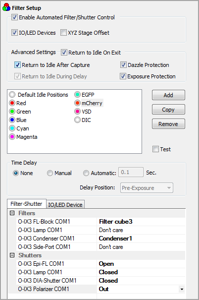
The Automate Filter and Shutter Control Setup Panel is found in the Device Pane and allows customization of a list of positions for each of the computer-controlled Filters and Shutters installed in the Current Profile. Filter and Shutter devices can be added to the current profile using the Device Setup tab of Current Profile's properties (accessed through the main window's File>>Current Profile... menu command).

A list of Filter and Shutter combinations is maintained in the Profile along with some parameters relating to each device when positioning for image capture. The Filter and Shutter Control Setup dialog includes:
Note: IO/LED Device and Stage Offset tabs will be hidden when deselected. If the automatic Filter and Shutter control is deselected, it is still be possible to select the added filter and shutter groups in various capture dialogs.
The Filter and Shutter List manages groups of Filter and Shutter settings, i.e. sets of configurations listing what state each of the installed Filter and Shutter devices needs to be placed in to obtain the particular lighting conditions necessary for the desired image.
Default Idle Positions is a group of filter and shutter settings defining the default positions for each of the installed filter and shutter devices. This group can be utilized during delays, between captures, etc. depending on the state of options such as Return to Idle Positions.
Filters are generally named for a observation method such a BF (brightfield), PH (phase contrast), DIC (differential interference contrast), etc. In the case of fluorescence imaging, filters are usually named and tinted for a specific fluorochrome (GFP, 510nm or Green). Right-click on the filter and select a tint to assign to the filter or select New to create a custom tint.
Hint: To rename a filter, simply "slow" double-click the filter in the list and type the name. This is the same method that is used in Windows Explorer to rename files in Windows operating systems.
Note: Configure newly added groups in the Filter and Shutter selection boxes. Selecting an item in the list will display the current position settings for the installed devices in the Filter and Shutter display boxes, where they can be modified.
For each filter setting, a programmable time delay can be inserted at one of three possible times in the image capture sequence:
The time delay can be automatic or manual.
The Selections for each of the installed Filter Devices are displayed in the Filter Selection box of the Filter Setup Menu. Each Installed Filter Device is listed in the left column of the box. Clicking on the Wavelength of any of the Filter Devices will pop-up a list of installed filters. Selecting the required filter will show the Wavelength and Position in the list. New filters are installed in the Current Profile.
Select the Don’t Care position when no movement is desired; i.e., leave the filter in the previous state.
The Selections for each of the installed Shutter Devices are displayed in the Shutter Selection box of the Filter Setup Menu. Each Installed Shutter Device is listed in the left column of the box. Clicking on the Status of any of the Shutter Devices will pop-up a list of shutter positions.
The positions available are defined by the way the Shutters were installed in the Current Profile. Each shutter is installed with one of four conditions:
Only those shutters installed as Active can have their position selected. Clicking on the Status of an Active shutter will toggle the status between Open, Closed and Don’t Care. Select the Don’t Care position when no movement is desired. The shutter will remain open if it was already open and remain closed if it was already closed.
Note: For some devices that do not have a physical shutter, it may be possible to use the Default Idle Position in the List as a shutter by blanking the filter position or driving to a inactive wavelength and using the Return to Idle Positions after Capture option.
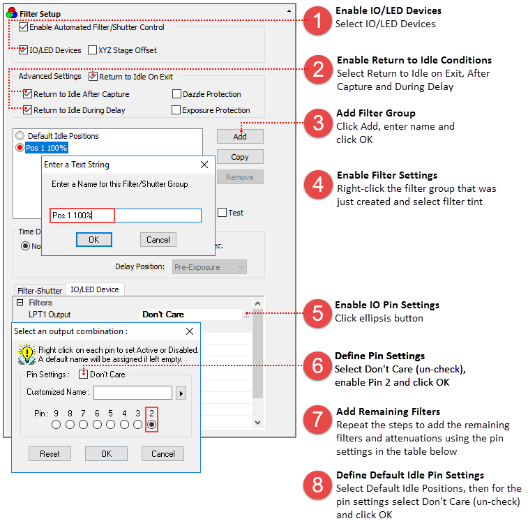
Filters and Shutters can be configured in a similar manner in the IO/LED Device tab, the difference is the devices are controlled using TTL. The way this works is that the filter device is configured in such a way that when it receives an input signal on pin 2 it performs action A and when it receives an input signal on pin 3 it performs action B. The filter device's actions are dependent upon which pin the input signal is on. For shutters the pin determines which shutter is being controlled and the action, being open or closed is controlled by the state (High or Low) of the input signal. In HCImage the setup is simple, for each filter in the list select the appropriate pin number for the filter device and set the state for each shutter. For an overview and instructions on setting up the CoolLED pE-4000 in HCImage, please click here.
Note: Configure newly added groups in the IO/LED Device tab in the Filter and Shutter selection boxes. Selecting an item in the list will display the current pin settings for the installed devices in the Filter and Shutter display boxes, where they can be modified.
Select the Stage Offset Tab to define an X, Y, Z offset for each filter and shutter position.
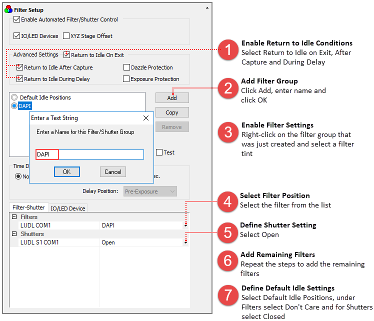
After the filter wheel and shutter have been added to the profile, go to Filter Setup in the Device pane and follow the instructions below.

Note: For some devices, such as LEDs that do not have a physical shutter, use the Default Idle Position in the List as a shutter by making the LEDs inactive and using the Return to Idle Positions after Capture option.
TTL can be used to control many types of devices. This example explains how to configure a Lambda DG-4 as an I/O Device controlled through the parallel port. In the Device pane go to Filter Setup and follow the instruction below.

| Filter Position | Attenuation | ||
|---|---|---|---|
| 100% | 50% | 33% | |
| 1 | Pin 2 | Pins 2 & 4 | Pins 2 & 5 |
| 2 | Pin 3 | Pins 3 & 4 | Pins 3 & 5 |
| 3 | Pins 2 & 3 | Pins 2, 3 & 4 | Pins 2, 3 & 5 |
| 4 | Pin 4 | Pin 5 | Pins 5 & 4 |